Should vs Shall vs Must

When I joined the API 682 1st Edition Taskforce in 1991, one of the fine points of writing that I had to learn was to use “shall” instead of “should” when writing standards.  “Shall” just was not, and still is not, a word in my day-to-day vocabulary.  My tendency was to think, say and write “(something or other) should be designed (made of, tested – whatever)” instead of “… shall be …”.

Using “shall” instead of “should” was stressed to the point that I came to believe that API did not allow the use of “should” at all.  Actually, API does allow the use of “should” and explains its use in its “API Document Format and Style Manual”.  Correct usage is also explained in the Foreword to API 682 4th Edition:

“As used in a standard, “shall” denotes a minimum requirement in order to conform to the specification. “

whereas

“… “should” denotes a recommendation or that which is advised but not required in order

to conform to the specification.”

API 682 4th Edition uses the word “should” a total of 183 times!  “Shall” is used 822 times.  When an API standard says you shall do something, it means that you are required to do so.  Seems clear, doesn’t it?

As it turns out, “shall” is not a word of obligation.  The Supreme Court of the United States ruled that “shall” really means “may” – quite a surprise to attorneys who were taught in law school that “shall” means “must”.   In fact, “must” is the only word that imposes a legal obligation that something is mandatory. Also, “must not” are the only words that say something is prohibited. 

Here are some references that say to use the word “must” instead of “shall”:

Frankly, the above references are so long and complex that they were of little help to me but perhaps someone with legal experience can decipher them.  Interestingly, many of the references themselves use “shall” a lot.

It seems that many federal documents are being revised by replacing “shall” with “must” to indicate a requirement.  I wonder if API will soon be doing the same?

Back-to-Back, Face-to-Face, Face-to-Back Orientations

The definitions for seal orientations have been tweaked a bit in order to make those definitions more general.  At first glance, this revision might seem to make the SealFAQs definitions differ from the API 682 definitions however, there really is no conflict.  Note that although SealFAQs includes much information about API 682, SealFAQs is much more general.  To save you a click or two, the revised definitions read

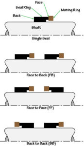
Back-to-back = Dual seal in which both of the seal rings are mounted between the mating rings.

Face-to-face = Dual seal in which both of the mating rings are mounted between the seal rings.

Face-to-back = Dual seal in which one mating ring is mounted between the two seal rings and one seal ring is mounted between the two mating rings.

FF FB BB Illustration

Although rotating springs are shown in the illustration above, the same definitions apply to seals having stationary springs or even to configurations mixing rotating and stationary springs.

The revised SealFAQs definitions now consider only the physical orientation of the seal rings and mating rings and not how the resulting configuration might be applied.  This is a much more general approach than is used in API 682 but is not in conflict with API 682.  In API 682:

The back-to-back configuration is used for Arrangement 3 and has the barrier fluid on the OD of both the inner and outer seals.

The face-to-face configuration is used for Arrangement 3 and has the barrier fluid on the OD of both the inner and outer seals.

The face-to-back configuration can be used for either Arrangement 2 or Arrangement 3 and has the barrier or buffer fluid on the ID of the inner seal and OD of the outer seal.

Outside of API 682, other schemes for pressurization and operation are sometimes used – although I must say that I don’t like some of them!

SealFAQs Statistics for December 2018

I almost forgot to publish statistics for December 2018!  The SealFAQs site is doing well but in 2019 I won’t be publishing statistics every month.  January 2019 views are at record highs so far.

SealFAQs statistics for December 2018.  December was a good month although not as good as November and October.  I blame the holiday season for the drop in viewers.

SealFAQs has been officially launched for a full year now.  In December, unique visitors dropped quite a bit from November and October.  Here are the statistics according to Awstats (Advanced Web Statistics).

SealFAQs had 2269 unique visitors during December and a total of 3970 visits (1.73 visits/visitor).  Visitors averaged looking at 2.2 pages per visit.  Bandwidth was 2.0 GB.  So the visits per visitor increased but pages per visit dropped a little.

Visits per day during December averaged 128; the most visits in a day was 196.   As usual, most people visit during the week and the middle part of the day.  There has always been a drop off in visits on the weekends and this drop off also occurred during the holiday season.

By far, the most visitors are from the United States and distantly followed by Thailand, India and Russia.

The average time of a visit decreased to 272 seconds in duration but 84% of all visits are still for less than 30 seconds.  It does appear that some people are logging in and staying on the site an hour or more – forgetting to log out or reading/studying?

Access to SealFAQs via search engines was based on 8 different keyphrases having 17 different words.  As in the past, piping plans were the most common search words.

I check SealFAQs for comments every day.  Almost no one has submitted a real comment but several bits of spam or faked comments show up daily.  The lack of comments and discussion continues to be troublesome to me.

Cooling Water on Seal Pots

Before retirement, I was regularly asked “Does that seal pot really need cooling water?”  The answer then, as now, usually was “Yes”.  Here’s a quick back-of-the envelope evaluation of a seal pot operating without cooling water and a simple guideline to when cooling water is needed.

The convective heat transfer coefficient to air is in the range of 2 to 5 Btu/hr sq ft°F depending on whether the wind is blowing or not.   This is very low heat transfer coefficient.  In comparison, water cooling coefficients are on the order of 50 to 300 Btu/hr sq ft °F.

If the surface temperature of the seal pot gets too hot then there can be a safety issue.  Many End Users do not want the pot to be at temperatures much higher than 150 °F or so.  This evaluation is based on a maximum seal pot (that is, buffer/barrier fluid) temperature of 150 °F.  Will the seal operate satisfactorily at a temperature hotter than 150 °F?  Almost certainly – the pot will just be hot.  Is the buffer/barrier fluid suitable for temperatures hotter than 150 °F?  That depends on the fluid but probably so.

Remember that the surface temperature of the pot will be hotter than that of the surrounding air.  If the pump and seal are to be operating in the summer then a summertime air temperature should be considered.  Also, for most places, sometimes the wind is not blowing.  Therefore, the base case is

Heat transferred = area x temperature difference x heat transfer coefficient; that is
Heat transferred from pot = pot area ft2 x (150 – 100) °F x 2 Btu/hr sq ft

The external area of a typical seal pot is (very roughly)

  • 2 gal –> 3 to 4 sq ft
  • 3 gal –> 4 to 5
  • 4 gal –> 6 to 7
  • 5 gal –> 7 to 8

So the base case heat transfer from an air cooled pot is roughly

  • 2 gal –> 300 to 400 Btu/hr
  • 3 gal –> 400  to 500
  • 4 gal –> 600 to 700
  • 5 gal –> 700 to 800

This is not very much heat transfer.  On a 50 °F day, with the wind blowing, those heat dissipation values could be multiplied by 5 but that is still not much heat transfer.  Of course, whatever heat is generated will be transferred by virtue of the seal pot temperature becoming as hot as necessary.

In addition to heat generation by the seal faces, there is heat absorbed from a hot pump into the buffer/barrier fluid; this is called heat soak.  For reference, according to API 682, the heat soak from a 200 °F pump to a 150 °F buffer/barrier is 1200 Btu/hr for a 2″ seal size pump.  Therefore, an air cooled pot should not be recommended even for a warm pump having small seals.

For tandem (unpressurized, Arrangement 2) seals, the usual requirement is that the seal pot has to dissipate the heat generated by the outer seal plus heat soak, if any.  As a point of reference, the outer seal of a tandem arrangement generates roughly 100 to 300 Btu/hr per inch of seal size at 3600 rpm (depending spring load, face width, materials, etc.).  Therefore, it turns out that the limits for an air cooled pot with Plan 52 on a hot summer day, no wind, 150 °F maximum allowable pot temperature  would be something like

  • 2 gallon pot –> 1.25″ seals and smaller
  • 3 gal –> 1.625″ seals and smaller
  • 4 gal –> 2.125″ seals and smaller
  • 5 gal –> 2.5″ seals and smaller

For double seals (Arrangement 3) using Plan 53, the usual requirement is that the seal pot must dissipate the heat from both seals plus heat soak, if any.  Therefore, an air cooled pot will almost never be adequate for Plan 53 since the minimum pot pressure must be at least 25 psig and heat loads would be more than double that of the tandem seals (Arrangement 2).  That is, heat loads for Plan 53 would be about 400 to 1200 Btu/hr per inch of seal size.

All the above calculations are very rough and very conservative but still representative.  In fact, the rough calculations readily demonstrate that most dual seal applications need water cooling and show why this is so.  But the rough estimate also shows that there is a place for air cooling and can provide some guidelines for defining those limits.

Based on the above analysis and estimates, here are some guidelines for application of cooling water:

  • Pump temperature above ambient — use water cooling
  • Plan 52, when pump temperature is ambient or cooler – use air cooling
    • 1800 rpm — pot size should be 1 gallon per inch of seal size (2 gallon minimum)
    • 3600 rpm — pot size should be 2 gallon plus 1 gallon per inch of seal size
  • Plan 53 — use water cooling

And a reminder:  Seal pots will always run hotter with oil (even the low viscosity synthetics) buffer/barrier fluids than with glycol/water solutions.

For those who really want to further investigate this question using more sophisticated calculations:  Good Luck!  There is not much information available.  A conservative approach is to order the seal pots with cooling coils but do not connect the cooling water to the coils unless proven necessary by actual operation.

Hydrostatic Pressure Test

Apparently, the rules and guidelines for conducting a hydrostatic test on pressure vessels – including pumps – are about to be changed.  Perhaps those rules have already been changed and I’ve simply missed hearing about them.  I blame that on retirement.

The hydrostatic test is the way in which pressure vessels are tested for leaks.  The test involves filling the vessel with a liquid, usually water, and pressurizing it to the specified test pressure.  In my career, the rule for determining the hydrostatic test pressure has been to simply multiply the Maximum Allowable Working Pressure (MAWP) by 1.5.  That is, suppose a certain vessel has an MAWP of 600 psig; it would be hydrostatically tested at 900 psig.  Of course, there are other details such as the duration of the test, variations based on operating temperature, etc.  But basically, the hydrostatic test pressure has been 1.5 x MAWP for many years – certainly since the 1950s.  However, it has not always been that way.

Here’s an interesting little anecdote that I was told many years ago.  I may not have it quite right and, for all I know, it may not even be true, but here goes.  In the 1970s, I was told that very long ago, the practice was to test pumps at 2 x MAWP.  Perhaps this was because pumps are manufactured from castings.  Anyway, there was a pump standards meeting (perhaps this was even an early form of an API standards meeting) and a requirement was written to hydrostatically test pumps at 1.5 x MAWP.  After the meeting, the chief engineer for a major pump manufacturer was buying drinks for everyone at the bar.  Surprised by his generosity, a fellow committee member remarked that the 2x hydrostatic test must have been difficult.  “Not at all”, said the chief engineer, “In fact, I just increased all my pressure ratings by 33%!”  That is, pumps previously rated for 600 psig MAWP but hydrostatically tested at 1200 psig could still be hydrostatically tested at 1200 psig but then rated for 800 psig MAWP!

I’ve been told that the multiplication factor for determining the hydrostatic test pressure will be changed from 1.5 to 1.3 according to the ASME Pressure Vessel Code Section VIII.  Apparently this will be applied to both pumps and piping.  The same multiplier will probably be used for API 682 reservoirs such as are used with Piping Plan 52 and 53.  The pertinent 4th Edition clauses for reservoirs now read:

8.3.6.2.8 The reservoir is part of the pump piping system. Unless otherwise specified or required by local code, the reservoir shall be designed, fabricated, and inspected in accordance with ISO 15649 or ASME B31.3 using piping components.

8.3.6.2.9 If the reservoir is built entirely of piping components, ISO 15649 or ASME B31.3 can be applied and provides adequate design for the reservoir just as it does for the pump suction and discharge piping. It is the user’s responsibility to ensure that local codes do not require that reservoirs be built in accordance with a pressure vessel code such as EN 13445 or ASME VIII, Division 1.

With this wording, the default is a pipe based reservoir but an ASME certified reservoir is an option.  I hope we will be able to continue this approach in 5th Edition but I’m uncertain about higher pressure reservoirs.  From my past experience, old notes and browsing, here’s what I’ve learned.

ASME Certified Pressure Vessels

ASME certified pressure vessel fabricators undergo a rigorous program to ensure compliance with the rules and regulations of the ASME Boiler and Pressure Vessel code.  For unfired pressure vessels, these requirements are given in ASME VIII, Division 1 (EN 13445).  There are two variations of certification:  “U” stamp and “UM” stamp.

“U”stamped pressure vessels are required to have a 3rd party ASME inspector review and approve the calculations as well as inspect certain stages during manufacture of the reservoir.  This inspector also witnesses the ASME hydrostatic test which, apparently, is now 1.3 x MAWP.  This means that U stamped vessels cannot be manufactured in advance; that is, the U stamped vessel is customized for a particular service, has a serial number and therefore cannot be a stocked item. The fabricator undergoes an ASME inspection every three years.

In contrast to the U stamped vessels, there is a “UM” stamped vessel which is also subject to the same ASME specifications.  However, the “UM” stamped vessel is limited to a maximum of 1.5 cubic feet for a 600 psig rating and 600 psig is the maximum permitted pressure for the UM stamp.  ASME 3rd party inspection is not required; therefore “UM” vessels can be manufactured in advance, they do not have a serial number and they can be stocked as an inventory item.  The UM fabricator is inspected annually by ASME.

Pipe Based Reservoirs

Pipe based reservoirs for API 682 sealing systems must be built entirely of piping components and ASME B31.3, “Process Piping”, (ISO 15649) is the governing standard.  As far as I can tell, ASME B31.3 now requires hydrostatic testing at 1.3 x MAWP.

Mechanical Seals

It should be noted that the mechanical seal is not considered to be part of the pump pressure vessel and therefore does not fall under the pressure vessel rules.  Seal manufacturers have several pressure ratings for their products.  API 682 recognizes a static pressure rating, a dynamic pressure rating and a hydrostatic pressure test rating (see the SealFAQs version of these definitions).  Each seal OEM seems to use a different and proprietary method for determining these pressure limits.


SealFAQs Statistics for November 2018

SealFAQs statistics for November 2018.  November was the best month, so far, of 2018 although realistically, only fractionally better than October.

SealFAQs has been officially launched for eleven months now.  In November, unique visitors increased quite a bit from previous months.  Here are the statistics according to Awstats (Advanced Web Statistics).

SealFAQs had 2675 unique visitors during November and a total of 3980 visits (1.48 visits/visitor).  Visitors averaged looking at 2.4 pages per visit.  Bandwidth was 2.4GB.  So the visits per visitor and pages per visit has remained about the same for several months. This means that many visitors do not make a return visit and also look at only a few pages.

Visits per day during November averaged 132; the most visits in a day was 199 – twice!.   As usual, most people visit during the week and the middle part of the day.  There has always been a drop off in visits on the weekends.

By far, the most visitors are from the United States and distantly followed by India and China.

The average time of a visit decreased to 283 seconds in duration but 82% of all visits are still for less than 30 seconds.  It does appear that some people are logging in and staying on the site an hour or more – forgetting to log out or reading/studying?

Access to SealFAQs via search engines was based on 9 different keyphrases having 23 different words.

I check SealFAQs for comments every day.  Almost no one has submitted a real comment but several bits of spam or faked comments show up daily.  The lack of comments and discussion continues to be troublesome to me.

The Development of the Stationary Metal Bellows Seal

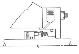
Figure 1. Early concept (ca 1976) of stationary metal bellows seal for low temperature.

Stationary metal bellows seals as we know them today were developed as part of a seal reliability program at Exxon’s Baton Rouge refinery in the 1970s.  The Exxon “Pump Team” was not satisfied with reliability and performance of seals in hot oil services because the oils decomposed and locked rotating flexible sealing elements in place.  Beginning in January 1976, prototype stationary metal bellows seals were designed, manufactured and assembled by the Exxon Pump Team using parts from various seal manufacturers fitted into custom assemblies manufactured in the Exxon machine ship.

The Exxon Pump Team tested 19 prototypes in many variations before deciding to turn over the designs and results to the seal manufacturers.  There was some consideration for seeking a patent but it was thought that commercial development of the concept would be better done by the seal OEMs.

I know this for a certainty because I was there and took an active part in this project.

The story of the stationary metal bellows seal is told in more detail on this page of SealFAQs.

API 682 Mating Ring Clearances

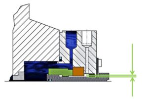
Mating Ring Clearance Illustration

Before the 4th Edition, API 682 did not specify a minimum clearance between the inside diameter of a stationary seal part and the outside diameter of a rotating seal part. The 4th Edition specifies this minimum clearance – typically the clearance between the sleeve OD and the mating ring ID. The clearances specified in 4th Edition are representative of standard clearances that have been used for decades.  I’ve written a historical perspective on how those sleeve to mating ring clearances came to be.

It should be emphasized that the minimum clearance specified in API 682 4th Edition applies only to equipment within the scope of the standard. Equipment outside that scope, such as non-cartridge seals, older pumps, non-API 610 pumps and certain severe services, might benefit from larger clearances.

SealFAQs statistics for October 2018

October was the best month, so far, of 2018.

SealFAQs has been officially launched for ten months now.  In October, unique visitors increased quite a bit from previous months.  Here are the statistics according to Awstats (Advanced Web Statistics).

SealFAQs had 2634 unique visitors during October and a total of 3769 visits (1.43 visits/visitor).  Visitors averaged looking at 2.3 pages per visit.  Bandwidth was up to 2.4GB.  So the visits per visitor and pages per visit has remained about the same for several months. This means that many visitors do not make a return visit and also look at only a few pages.

Visits per day during October averaged 121; the most visits in a day was 166.   As usual, most people visit during the week and the middle part of the day.  There has always been a drop off in visits on the weekends.

By far, the most visitors are from the United States and distantly followed by India and China.

The average time of a visit decreased to 304 seconds in duration but 80% of all visits are still for less than 30 seconds.  It does appear that some people are logging in and staying on the site an hour or more – forgetting to log out or reading/studying?

Access to SealFAQs via search engines was based on 16 different keyphrases including, as usual, several searches for information on piping plans.

I check SealFAQs for comments every day.  Almost no one has submitted a real comment but several bits of spam or faked comments show up daily.  The lack of comments and discussion continues to be troublesome to me.

API 682 “Engineered Seals”

The term “Engineered Seal” is widely misused and misunderstood with respect to API 682.  Let’s see how this came about.

API 682 imposes a wide range of design details for mechanical seals including materials, clearances, and design elements; however, it is not all inclusive of all seals and services. The 4th Edition Taskforce believed that this subset of details was prudent for seals which would be applied within the scope of the standard.   At the same time, the Taskforce recognized that at higher pressures, temperatures, speeds, or sizes the design details of the standard might be inappropriate for the intended application.   Outside of this scope, the seal OEM is permitted, even encouraged, to deviate from the prescribed requirements and to “engineer” a seal with specific characteristics that are appropriate for the specific out-of-scope application. By definition, this special seal will then not fall into the strict definition of a Type A, B or C seal – it is an Engineered Seal.

So, what is the scope of API 682 4th Edition and what is the official definition and description of an “Engineered Seal”?

The Scope of API 682 4th Edition is, or should be, given in Section 1, “Scope”, of the standard.  As written in Section 1, the scope includes pump shaft diameters between 0.75 and 4.3 inches; unfortunately, Section 1 does not address pressure, temperature or speed.

The official definition of an “Engineered Seal” per API 682 4th Edition, Clause 3.1.29 is:

Mechanical seal for applications with service conditions outside the scope of this standard.

NOTE Engineered seals are not required to meet any of the design or testing requirements of this standard. See 4.1.3 and A.1.2.

Why are Engineered Seals not required to meet any of the design or testing requirements of API 682?  Simple: standards cannot impose requirements on things that are outside the scope of the standard.  For example, a standard limited to a scope of, say, 600 psig would not state “for higher pressures, double the thickness of everything”.   Similarly, API 682 cannot state “Even though a seal may not be intended to be in accordance with this standard, it still shall meet the design and testing requirements of this standard”.

Section 4 is about sealing systems.  Clause 4.1.3 defines seal types — A, B and C — and notes that Type A and B are suitable for temperatures up to 350 °F whereas Type C is for temperatures up to 750 °F.  Clause 4.1.3 then states that seals outside the scope of Type A, B and C are termed engineered seals.  Although “Engineered Seal” is sometimes written as “ES”, there actually is no “Type ES” seal.  Seal type is either Type A, Type B or Type C.

It is worthwhile to note that pressure limits are included in the definition of seal category which is given in Clause 4.1.2.  Category 1 is limited to 500 °F and 300 psig whereas Category 2 and 3 are limited to 750 °F and 600 psig.  These limits are usually taken as part of the scope of API 682 but were not included in Section 1.

Annex A is an informative annex entitled “Recommended Seal Selection Procedure”.  However, since Annex A is informative, it cannot not impose any requirements.  Clause A.1.2 is entitled “Additional Engineering Required” and is a list of eleven concerns which might provide reason for a more detailed engineering review of the seal.  The list includes size, speed, temperature, pressures and seal chambers that are outside the scope of API 682 4th Edition.  Again, this list is informative, not normative.

To my way of thinking, an Engineered Seal is simply an “other” with respect to API 682 and shows attention to detail for a particular service that is not otherwise included in the scope of API 682. As a practical matter, API 682 Engineered Seals typically have some basis in API 682 — certainly that is the expectation of the Purchaser.  But again, as noted previously, API 682 cannot impose requirements on these out-of-scope designs.

An otherwise true API 682 seal is still an API 682 seal even if the seal chamber does not precisely conform to the API 682/610 dimensions.  Here is an example:  Suppose a seal OEM has designed a product that (somehow!) fulfills every requirement of API 682 when fitted into the proper seal chamber.  However, someone wishes to use this API 682 seal in a pump having a smaller seal chamber.  The API 682 seal fits into the chamber but its clearances no longer meet API 682 requirements.  The seal OEM could

  • Offer its standard API 682 design but take exception to API clearances
  • Offer a custom version of its standard API 682 design that meets API clearances in this particular pump but
    • Has a reduced pressure rating
    • Does not have multi-point injection
    • , etc.

The “custom” seal would be an API 682 “Engineered Seal”.  It is (most likely) a one-off design that has never been tested.  In a similar manner, an existing API 682 seal might be tweaked (materials, balance ratio, flush design, etc.) for somewhat higher pressures or temperatures as a one off “Engineered Seal” but never tested – it would be an Engineered Seal.

I hope that the 5th Edition of API 682 does a better and more concise job of defining the scope of API 682 as well as an “Engineered Seal”.  I believe that the “scope” of 5th Edition is likely to be clarified as well as expanded and therefore the need for “Engineered” seals will be reduced.  I’m on the taskforce and will be trying to do my part to make this happen.