Category Archives: pusher seal

Mechanical Seals in Chaos

In retirement, I’ve had time to contemplate the meaning of life and mechanical seals.  With mechanical seals, as with life, things have not always worked out the way I thought they would.   I’ve come to believe that mechanical seals, like life, are near-chaotic systems.

Chaos is sometimes defined as complete confusion and disorder.  If Chaos is complete confusion then Chaos Theory is the mathematics that attempt to explain it – or at least show how Chaos cannot be explained or controlled. 

One characteristic, perhaps the easiest to understand, is that chaotic systems have such a strong dependence on initial conditions that the outcome appears to be random.  Chaos was summarized by Edward Lorenz as “When the present determines the future, but the approximate present does not approximately determine the future.”

Non-linear systems sometimes respond in an apparent chaotic manner.  It is important for engineers to realize that our day-to-day mathematical methods often use extremely linearized versions of non-linear systems.  Anyone who applied engineering mathematics using a slide rule can readily appreciate this linear simplification; however, many computer programs still use the same linear simplifications that we fully mature engineers learned to use on our slide rules.

Examples of potentially chaotic simple systems include:

    • Spring-mass system (with non-linear spring) with damping
    • Fluid flow, especially for turbulent flow regimes
    • Any process relying on friction
    • Any process having wear
    • A dripping faucet
    • Stick-slip sliding
    • Thermosiphon systems (flow direction can reverse).

Any of the above examples seem familiar?  Let’s see where Chaos Theory might apply to mechanical seals:

    • All seals have some sort of spring; spring force is a function of seal position (setting)
    • Metal bellows seals have little damping
    • O-rings provide damping but are dependent on lubrication and surface finish
    • Fluid flow patterns around seals are dependent on flush rate (and fluid type, rpm, clearances, etc.)
    • Seal face friction is dependent on material combinations and lapping (not to mention speed, load, fluid, leakage, etc.)
    • Seal face wear rate depends on face load, friction, materials, lapping, fluid, leakage, etc.
    • Shrink fits affect seal face flatness and waviness
    • Stick-slip sliding between seal faces is a well-known phenomenon, especially with metal bellows seals
    • Piping plans for seals sometimes rely on thermosiphon effects.

Not to mention venting!

We certainly want and expect a consistent performance from mechanical seals.  Let’s look at how this might be accomplished.

An often overlooked aspect of mechanical seals is the surface finish (roughness) of the faces.  Most people know the importance of lapping a seal face to near perfect flatness but the surface finish is also extremely important.  Surface finish is measured in millionths of an inch and can vary considerably with the material, manufacturer, even batch.  Also, many suppliers do not check surface finish regularly but rely on the manufacturing process for consistency.  Some suppliers may not even have the equipment to check surface finish.

The flush rate to a seal is important not only for traditional heat balance considerations but for establishing the flow pattern around the seal.   More – or less – flush is often given credit for solving seal reliability problems when the effect may be due to flow pattern and not traditional heat balance.

Other approaches to minimizing chaos in mechanical seal performance include: 

    • Designs employing damping (“pusher” seals)
    • Monolithic designs instead of shrink fitted designs
    • Cartridge seals have a more consistent assembly and therefore consistent spring load
    • Consistency in selecting materials for repaired seals
    • Don’t rely on thermosiphon effects
    • Vent!  Vent! Vent!  Don’t attempt to startup with air in the system.

A more appropriate title for this post might have been “Mechanical Seals and Chaos Theory”; however, that title appears a bit more academic than this post actually is.  Besides, I really don’t know Chaos Theory but surely it applies to mechanical seals!  Perhaps someone with more up-to-date skills in mathematics will apply those skills to studies of mechanical seals and provide guidelines to preventing chaos. 

Thrust Load from Seals

The pressure surrounding the mechanical seal and its shaft sleeve imposes an axial force – a thrust – on the shaft.  This thrust load and direction can be determined by summing the products of the various pressures and areas of the seal and sleeve.  Fortunately, many of these products cancel each other out and the thrust load can be computed in a simple manner. 

The method shown below for calculating thrust load is taken from Chapter 17, “Seal Thrust Loads on Pump Shafts”, of Mechanical Seals for Pumps:  Application Guidelines from the Hydraulic Institute and Fluid Sealing Association.   Only the thrust load for single pusher seals is shown in this post but the book includes dual seals and bellows seals.

The general idea is that there is a hydraulic area between the balance diameter of the seal and the shaft upon which the seal chamber pressure acts to produce an axial thrust.  This hydraulic area is given by

where

    • A is the hydraulic “thrust” area, inch2
    • Db is the balance diameter of the seal, inch
    • Ds is the OD of the shaft, inch.

The thrust force is the product of the seal chamber pressure and thrust area.

The location of the balance diameter is illustrated below.

For many seals, the balance diameter can be estimated from the shaft size as follows:

  • Classic rotating seal:  shaft diameter plus 1/2” to 5/8”
  • Inverted rotating seal (made into stationary seal):  shaft diameter plus 5/8” to 1”
  • Stationary seal:  shaft diameter plus 5/8” to 1”.

These approximations to the balance diameter can be made because, typically, radial thicknesses, radial steps and even O-ring cross sections are based on 1/8” increments.  Radial clearances are often based on 1/16”; seals with large radial clearances may also have larger balance diameters.  Another variation comes from the shaft diameter not being an exact 1/8” increment and the sleeve may be used as an “adapter”.  Of course, the exact balance diameter depends on the seal design, thicknesses, clearances, etc. and the seal manufacturer should be consulted.

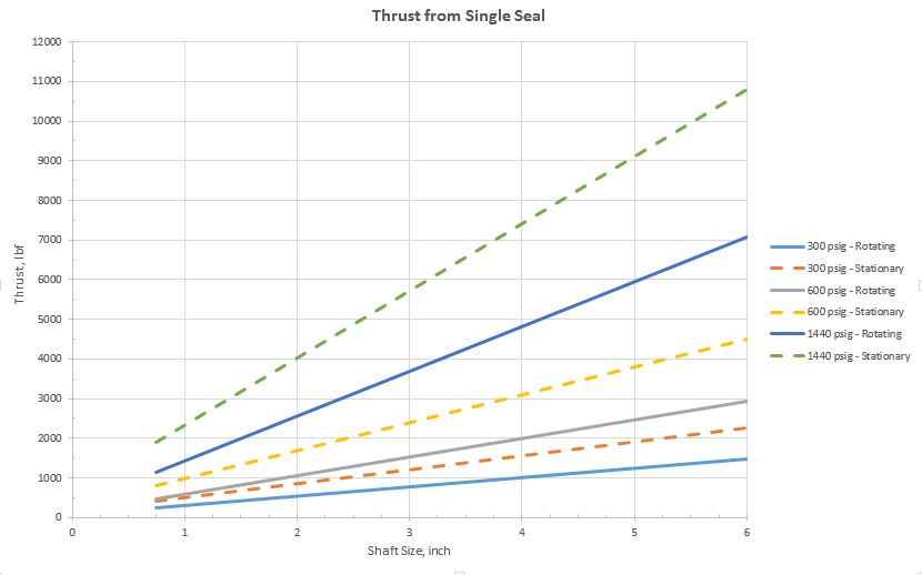
So, how much thrust is produced by the seal?  Sometimes, quite a lot – especially for large seals at high pressures.  The graph below is based on a classic rotating seal with balance diameter 1/2” larger than the shaft and a stationary seal with balance diameter 3/4” larger than the shaft.

Obviously, the thrust load estimated here for a stationary seal exceeds that of a rotating seal but this may not always be the case.  Again, the details of the seal design must be checked.  However, it is often the case that the thrust load from a stationary seal is larger than that from a rotating seal; therefore, it is best to consider a stationary seal configuration when making general assumptions about thrust loads.

This thrust load is transmitted to the shaft – typically by set screws – but devices such as pins, slots, grooves, split rings, etc. are sometimes used.  Therefore this thrust load is added to the thrust load imposed on the pump bearings.  Note that if the pump uses two seals (one on the driven end and one on the non-driven end) then the net thrust load from the seals that is imposed on the bearings may be zero.

Eventually, this blog post will make its way into the design pages of SealFAQs.  In a later post, we’ll take a look at the thrust capacity of set screws.

Accessories for Cell Phone Cameras

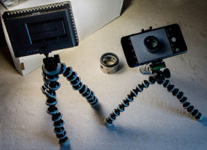
iPhone 7+ and LED light on Joby Gorillapods

We photographers certainly love our accessories!  Here are some suggestions for accessories to help get the image you want with your cell phone.

Tripod

Although many people prefer not having to deal with a tripod, it is still one of the first and best accessories for photography.   In this discussion, since the subject is cell phone photography, it is implied that the tripod be small and lightweight.  Also needed is a means of attaching the cell phone to the tripod.

One of the Joby Gorillapods seems ideal for cell phone photography.  I’m currently using this one with my iPhone 7+.  To use the cell phone with a more conventional tripod, you’ll need a cell phone mount .

When using the cell phone mounted on a tripod, I prefer to use a 2 second delay to trip the shutter.  This helps to prevent camera/tripod vibration from my touch.  For my iPhone, setting the shutter delay also automatically switches the camera to a 10 shot burst mode – which is not always desirable.  Unfortunately, there is no way to turn off this burst mode; however, a workaround is to turn on the “HDR” mode as well.  With HDR mode, only two shots are taken:  one shot is normal, the other HDR.  Actually, the HDR image is often a good one.

Diffuser and Reflector

A diffuser can soften the light and prevent hot spots when the subject is in bright sunlight.   You can make one with a translucent trash bag taped to a cardboard frame.

A reflector placed on the opposite side of the light source helps distribute the light and reduce shadows.  The reflector can be a piece of copy paper (or bring along a large sheet of foamboard).

Diffusers and reflectors can be difficult to handle – another reason to free up your hands by placing the camera on a tripod.

Backdrop

A backdrop can hide that unwanted background clutter but can be difficult to set up.  A painter’s drop cloth and a few spring clamps can be useful.  For small subjects, the backdrop and reflector can be a sheet of paper.

Lights

A small, inexpensive, battery powered LED light is probably the best way to add light to the scene.    I use one like this with a rechargeable battery (separate purchase); similar ones can be purchased for about $30. With the camera on a tripod, move the light around to find the best angle and distance to light the scene.  Unfortunately, a battery lasts only about an hour.  Add a reflector on the opposite side of the light to balance the lighting.

The original Joby Gorillapod is useful for holding the LED light.

Macro lens

There are a number of macro lenses available for cell phone close-up photography.  Some of these lenses are very powerful; however, getting good lighting can be a problem.  When using a macro lens on a cell phone, the lens will probably be only about an inch from the subject area.  As far as I’m concerned, if you buy a macro lens, you might as well buy a light or two while you’re at it.

Here are some macro lenses that are popular and appear useful:

I recently got the Olloclip kit of macro lenses and am trying to decide whether I like them or not.  I’ll probably get one or two of the less expensive lenses and compare them in a separate blog post.

Coming up

The next post will be about cell phone camera apps.