Category Archives: bellows seal

Mechanical Seals in Chaos

In retirement, I’ve had time to contemplate the meaning of life and mechanical seals.  With mechanical seals, as with life, things have not always worked out the way I thought they would.   I’ve come to believe that mechanical seals, like life, are near-chaotic systems.

Chaos is sometimes defined as complete confusion and disorder.  If Chaos is complete confusion then Chaos Theory is the mathematics that attempt to explain it – or at least show how Chaos cannot be explained or controlled. 

One characteristic, perhaps the easiest to understand, is that chaotic systems have such a strong dependence on initial conditions that the outcome appears to be random.  Chaos was summarized by Edward Lorenz as “When the present determines the future, but the approximate present does not approximately determine the future.”

Non-linear systems sometimes respond in an apparent chaotic manner.  It is important for engineers to realize that our day-to-day mathematical methods often use extremely linearized versions of non-linear systems.  Anyone who applied engineering mathematics using a slide rule can readily appreciate this linear simplification; however, many computer programs still use the same linear simplifications that we fully mature engineers learned to use on our slide rules.

Examples of potentially chaotic simple systems include:

    • Spring-mass system (with non-linear spring) with damping
    • Fluid flow, especially for turbulent flow regimes
    • Any process relying on friction
    • Any process having wear
    • A dripping faucet
    • Stick-slip sliding
    • Thermosiphon systems (flow direction can reverse).

Any of the above examples seem familiar?  Let’s see where Chaos Theory might apply to mechanical seals:

    • All seals have some sort of spring; spring force is a function of seal position (setting)
    • Metal bellows seals have little damping
    • O-rings provide damping but are dependent on lubrication and surface finish
    • Fluid flow patterns around seals are dependent on flush rate (and fluid type, rpm, clearances, etc.)
    • Seal face friction is dependent on material combinations and lapping (not to mention speed, load, fluid, leakage, etc.)
    • Seal face wear rate depends on face load, friction, materials, lapping, fluid, leakage, etc.
    • Shrink fits affect seal face flatness and waviness
    • Stick-slip sliding between seal faces is a well-known phenomenon, especially with metal bellows seals
    • Piping plans for seals sometimes rely on thermosiphon effects.

Not to mention venting!

We certainly want and expect a consistent performance from mechanical seals.  Let’s look at how this might be accomplished.

An often overlooked aspect of mechanical seals is the surface finish (roughness) of the faces.  Most people know the importance of lapping a seal face to near perfect flatness but the surface finish is also extremely important.  Surface finish is measured in millionths of an inch and can vary considerably with the material, manufacturer, even batch.  Also, many suppliers do not check surface finish regularly but rely on the manufacturing process for consistency.  Some suppliers may not even have the equipment to check surface finish.

The flush rate to a seal is important not only for traditional heat balance considerations but for establishing the flow pattern around the seal.   More – or less – flush is often given credit for solving seal reliability problems when the effect may be due to flow pattern and not traditional heat balance.

Other approaches to minimizing chaos in mechanical seal performance include: 

    • Designs employing damping (“pusher” seals)
    • Monolithic designs instead of shrink fitted designs
    • Cartridge seals have a more consistent assembly and therefore consistent spring load
    • Consistency in selecting materials for repaired seals
    • Don’t rely on thermosiphon effects
    • Vent!  Vent! Vent!  Don’t attempt to startup with air in the system.

A more appropriate title for this post might have been “Mechanical Seals and Chaos Theory”; however, that title appears a bit more academic than this post actually is.  Besides, I really don’t know Chaos Theory but surely it applies to mechanical seals!  Perhaps someone with more up-to-date skills in mathematics will apply those skills to studies of mechanical seals and provide guidelines to preventing chaos. 

API 682 is Not a General Purpose Standard

In spite of all its excellent specifications, recommendations, tutorials, etc., etc., API 682 is not a general purpose standard for mechanical seals.  Here is a partial list of seals that API 682 does not address:

  • large seals
  • high pressures
  • mixer seals
  • rotary pump seals
  • wedge/chevron/ucup
  • outside mounted
  • common mating ring
  • shaft mounted
  • hook sleeve mounted
  • automotive water pump seals
  • stern tube seals
  • split seals
  • elastomeric bellows seals.

It appears that the 5th Edition of API 682 will include somewhat larger seals and higher pressures.  Mixers and rotary pumps could, of course, use API 682 seals provided those seals would fit into the seal chamber.  Wedges, chevrons or U-cups for dynamic secondary sealing elements were intentionally omitted in favor of O-rings.  Outside mounted seals were intentionally omitted in favor of inside mounted seals.  Shaft mounted seals and hook sleeve mounted seals were omitted in favor of cartridge mounted seals.  Dual seals using a common mating ring were omitted in favor of requiring a mating ring for each seal ring.  Automotive water pump seals as well as similar small utility seals and stern tube seals are far outside the scope of API 682.  Split seals have very different design for special applications and were never considered for inclusion in API 682.

Interestingly, API 682 does not address one of the earliest, most popular and proven mechanical seals:  the elastomeric bellows seal.  The omission of elastomeric bellows seals was intentional because some members of the 1st Edition Taskforce felt that elastomeric bellows seals were difficult to install.  This can be true; however, since API 682 considers only cartridge seals, installation of elastomeric bellows seals is simplified and furthermore would be done by the seal OEM.

Elastomeric Bellows Seal

In the mid 1930’s Crane Packing Company licensed a mechanical seal design from Chicago Rotary Seal. By the late 1930s, mechanical seals began to replace packing on automobile water pumps.  At first only the more expensive automobiles used mechanical seals in the water pump. The famous Jeep of WWII used a Crane elastomeric bellows seal in the water pump.  After WWII, all automobile water pumps used mechanical seals. Through several Crane patents, their design evolved into the full convolution elastomeric bellows seal of today.            

In 1943, under the direction of Carl E. Schmitz and designed by Russ Snyder, Crane Packing Company began work on what became its Type 1 and Type 2 rubber bellows mechanical seals.  Don Piehn, a draftsman still in high school, did the detailed drawings.  The Type 1 and Type 2 seal names were adopted about 1946.  Prior to 1946, Crane seals did not have number/type names.  The Crane seals that had been used in WWII jeeps and later other automobile water pumps came to be called the Type 3 and Type 4 but actually preceded the Type 1 and Type 2. 

Today, there are many manufacturers of elastomeric bellows seals.  Elastomeric bellows are very popular and also very reliable but they are not considered by API 682.

The Development of the Stationary Metal Bellows Seal

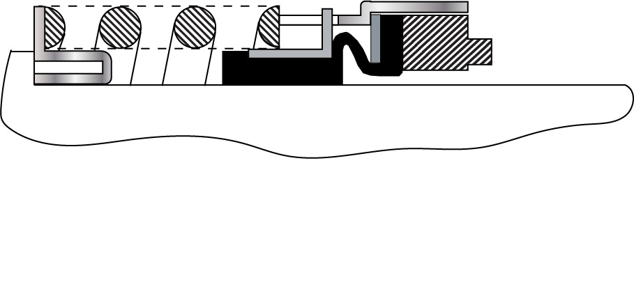
Figure 1. Early concept (ca 1976) of stationary metal bellows seal for low temperature.

Stationary metal bellows seals as we know them today were developed as part of a seal reliability program at Exxon’s Baton Rouge refinery in the 1970s.  The Exxon “Pump Team” was not satisfied with reliability and performance of seals in hot oil services because the oils decomposed and locked rotating flexible sealing elements in place.  Beginning in January 1976, prototype stationary metal bellows seals were designed, manufactured and assembled by the Exxon Pump Team using parts from various seal manufacturers fitted into custom assemblies manufactured in the Exxon machine ship.

The Exxon Pump Team tested 19 prototypes in many variations before deciding to turn over the designs and results to the seal manufacturers.  There was some consideration for seeking a patent but it was thought that commercial development of the concept would be better done by the seal OEMs.

I know this for a certainty because I was there and took an active part in this project.

The story of the stationary metal bellows seal is told in more detail on this page of SealFAQs.

Using Your Cell Phone Camera

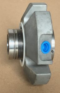
A cartridge seal.

Your cell phone can be useful when documenting equipment failures, repairs, etc.  In fact, most readers have probably already used their cell phones to do so.  With the cell phone, you can dictate notes, record video or take still photographs.  This post is about improving those still photographs.

The advantages of using your cell phone camera to record damaged part information are

  • Always with you
  • More than adequate quality
  • Easy to use
  • Easy to send images to others.

I’m currently using an iPhone 7+ and really appreciate the quality and new features of its camera.  I especially like the telephoto (2x) lens.  Learn to use the features of your cell phone camera.   Here are some tips for getting good images from a cell phone camera without using additional auxiliary equipment:

  • Set focus point yourself, don’t rely on the camera autofocus
  • Zoom in (use 2x dual lens if available)
  • White Balance (color balance for the light source)
  • Adjust exposure manually, don’t rely on camera to set exposure
  • 2 second delay will help to avoid camera movement.

For more detailed information, especially with the iPhone, check out https://iphonephotographyschool.com/iphone-camera-controls/.

Remember that pictures you take will be used to tell the story of the failure or repair.  Be sure to establish the scene with the “big picture”.  Include some shots of components or areas before going too far with extreme close-ups or macros.  For example, in the report, you’ll want to be able to write things like:

  • Here’s the complete cartridge seal when first removed from the pump (the big picture)
  • Here’s the retainer (a component)
  • Notice the fretting inside the retainer (close-up of damage).

Clean up the background.

Remember the saying “90% of photography is moving furniture!” and apply this thought to removing the junk and clutter from the background of your photo.  Use cardboard, shop rags or copy paper for a background or to hide the clutter.

Fill the Frame

Move the camera in close and/or use the dual lens so that the screen is filled with the subject image.  This will save editing/cropping time and also produce a better image.  By filling the frame, you also allow for extracting a “macro” during editing.

Macros

Although macro lenses are available for cell phone cameras, those will be discussed in the next blog.  Most of the necessary documentation photos will not be macros or even close-ups but the camera can be moved very close to the subject to record details.   In post processing (editing) you can crop and zoom in for a “macro” image of details.

Don’t use the flash

The cell phone flash will produce hot spots on the image; turn the flash off and try to find good lighting.   Indirect light near a door or window can be very helpful.  If possible, move the parts outdoors on a cloudy day.

Select the best images

Get many pictures from different angles and distances, then select and use only the best ones.

Coming up

So far, the discussion has not included auxiliary equipment such as tripods, lenses and lighting.  Auxiliary equipment will be discussed in the next blog.