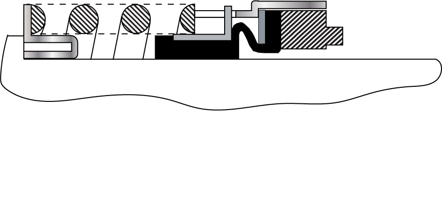
SEALFAQS STATISTICS FOR 2019

The SealFAQs site did well in 2019 even though I sort of neglected it the past few months.  SealFAQs is alive and well and I have a number of updates and articles to add.

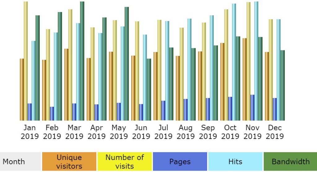
SealFAQs has been officially launched for two full years.  Here are the statistics for 2019 according to Awstats (Advanced Web Statistics):  SealFAQs had 33,020 unique visitors during 2019 and a total of 49,521 visits (1.5 visits/visitor).  Visitors averaged looking at 3 pages per visit.  Total bandwidth was 26 GB. 

Most days, SealFAQs has about 120 to 150 visitors but it is not unusual to have around 200 visitors. The most visits in a day during 2019 was 305.   As usual, most people visit during the week and the middle part of the day.  There has always been a drop off in visits on the weekends and during a holiday season.

By far, the most visitors to SealFAQs are from the United States and distantly followed by Thailand, India, Russia, Ukraine, Sweden, Canada, Great Britain and Germany.

The average time of a visit to SealFAQs is about 4 to 5 minutes in duration but this average is probably because a few people log in for hours.  More than 80% of all visits are for less than 30 seconds. 

Access to SealFAQs via search engines is usually based on key phrases related to piping plans. 

I check SealFAQs for comments every day.  SealFAQs finally has some legitimate comments instead of the bits of spam or faked comments that show up daily. 

I was especially pleased to have added a history of John Crane – the Person during 2019. 

Seal Codes

22A-PFR-075-11/52

Anyone recognize the above line?  This is a seal code from API 682 4th Edition.  A seal code is an abbreviated method of communicating the basic specification for the mechanical seal. Sadly, the seal code has been changed with every edition of API 682.  Fortunately, the new code, described in API 682 4th Edition Annex D, is the best to date and includes some concepts and codes from the historical API 610 seal code. The new code uses eight fields:

  • Seal category
  • Seal arrangement
  • Seal type
  • Containment device
  • Gasket material
  • Face material
  • Approximate shaft size (in millimeters)
  • Piping plan

For example, based on the 4th edition codes, a seal code of 31B-LIN-100-53A indicates:

  • 3 – Category 3 seal
  • 1 – Arrangement 1 seal
  • B – Type B seal
  • L – Floating bushing
  • I – Perfluoroelastomer (FFKM) secondary seals
  • N – Carbon (vs. reaction-bonded silicon carbide)
  • 100 – Installed on a nominal 75 mm shaft
  • 53A – Plan 53A

Recently, a visitor to SealFAQs was attempting to find information about the API seal code.  I thought sure seal codes had been included as a SealFAQs page but was surprised to find that I had neglected to do so.  That oversight has been corrected and SealFAQs now includes both the API 682 4th Edition seal code and the old API 610 (pump standard) seal code.

Mechanical Seals in Chaos

In retirement, I’ve had time to contemplate the meaning of life and mechanical seals.  With mechanical seals, as with life, things have not always worked out the way I thought they would.   I’ve come to believe that mechanical seals, like life, are near-chaotic systems.

Chaos is sometimes defined as complete confusion and disorder.  If Chaos is complete confusion then Chaos Theory is the mathematics that attempt to explain it – or at least show how Chaos cannot be explained or controlled. 

One characteristic, perhaps the easiest to understand, is that chaotic systems have such a strong dependence on initial conditions that the outcome appears to be random.  Chaos was summarized by Edward Lorenz as “When the present determines the future, but the approximate present does not approximately determine the future.”

Non-linear systems sometimes respond in an apparent chaotic manner.  It is important for engineers to realize that our day-to-day mathematical methods often use extremely linearized versions of non-linear systems.  Anyone who applied engineering mathematics using a slide rule can readily appreciate this linear simplification; however, many computer programs still use the same linear simplifications that we fully mature engineers learned to use on our slide rules.

Examples of potentially chaotic simple systems include:

    • Spring-mass system (with non-linear spring) with damping
    • Fluid flow, especially for turbulent flow regimes
    • Any process relying on friction
    • Any process having wear
    • A dripping faucet
    • Stick-slip sliding
    • Thermosiphon systems (flow direction can reverse).

Any of the above examples seem familiar?  Let’s see where Chaos Theory might apply to mechanical seals:

    • All seals have some sort of spring; spring force is a function of seal position (setting)
    • Metal bellows seals have little damping
    • O-rings provide damping but are dependent on lubrication and surface finish
    • Fluid flow patterns around seals are dependent on flush rate (and fluid type, rpm, clearances, etc.)
    • Seal face friction is dependent on material combinations and lapping (not to mention speed, load, fluid, leakage, etc.)
    • Seal face wear rate depends on face load, friction, materials, lapping, fluid, leakage, etc.
    • Shrink fits affect seal face flatness and waviness
    • Stick-slip sliding between seal faces is a well-known phenomenon, especially with metal bellows seals
    • Piping plans for seals sometimes rely on thermosiphon effects.

Not to mention venting!

We certainly want and expect a consistent performance from mechanical seals.  Let’s look at how this might be accomplished.

An often overlooked aspect of mechanical seals is the surface finish (roughness) of the faces.  Most people know the importance of lapping a seal face to near perfect flatness but the surface finish is also extremely important.  Surface finish is measured in millionths of an inch and can vary considerably with the material, manufacturer, even batch.  Also, many suppliers do not check surface finish regularly but rely on the manufacturing process for consistency.  Some suppliers may not even have the equipment to check surface finish.

The flush rate to a seal is important not only for traditional heat balance considerations but for establishing the flow pattern around the seal.   More – or less – flush is often given credit for solving seal reliability problems when the effect may be due to flow pattern and not traditional heat balance.

Other approaches to minimizing chaos in mechanical seal performance include: 

    • Designs employing damping (“pusher” seals)
    • Monolithic designs instead of shrink fitted designs
    • Cartridge seals have a more consistent assembly and therefore consistent spring load
    • Consistency in selecting materials for repaired seals
    • Don’t rely on thermosiphon effects
    • Vent!  Vent! Vent!  Don’t attempt to startup with air in the system.

A more appropriate title for this post might have been “Mechanical Seals and Chaos Theory”; however, that title appears a bit more academic than this post actually is.  Besides, I really don’t know Chaos Theory but surely it applies to mechanical seals!  Perhaps someone with more up-to-date skills in mathematics will apply those skills to studies of mechanical seals and provide guidelines to preventing chaos. 

Plan 31 and Cyclone Separators

Although mechanical seals are used in all sorts of dirty fluids, it is well established that reliability is best when the fluid is clean.  Therefore, there is a great incentive to provide a clean fluid flush for seals in dirty services.  Piping Plan 31 is intended to clean up a dirty fluid to provide a clean flush to the seals.  Frankly, I don’t particularly care for Plan 31 and have rarely used or recommended it.

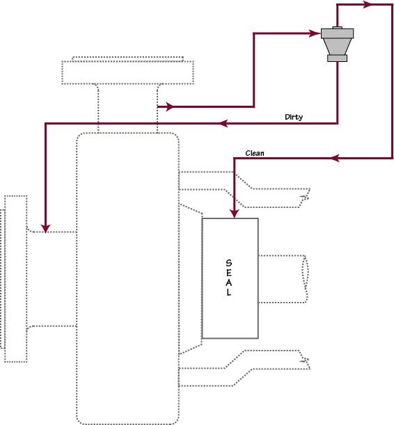
Plan 31
Plan 31

Recently I was asked a question about Plan 31 and realized that my description in SealFAQs was somewhat lacking so I’ll be revising and expanding that page.

Plan 31 relies on a “cyclone separator”, sometimes called an “abrasive separator”, or “hydrocyclone” to remove the dirt from the process fluid.  I’ve always preferred the term “cyclone separator” because it gives me a mental image of how the separation works.

In Plan 31, the pumped (dirty) product flows to a cyclone separator from the discharge of the pump.  The cyclone separator, uh, separates the pumpage into clean and dirty streams by using centrifugal force.  The clean fluid stream is routed out the top of the separator and into the seal chamber while the now concentrated dirty fluid stream is routed back to pump suction.  Roughly speaking, the clean and dirty steams are approximately equal in flow rate; that is, a 50/50 split.

The late Robert Watkins of Chevron absolutely hated Plan 31.  More specifically, he hated cyclone separators.  One day Robert and I were teaching a seals class when, to my astonishment, I realized that Robert was saying that a cyclone separator should be purchased for every pump!  He then laughed and said “… and it should be fastened to the motor with baling wire!”  His theory was that, after having bought a cyclone separator for each pump, the seal salesman would leave him alone.  Plus, he could look everyone in the eye and say “Yes, we have a cyclone separator at that pump.”

I’ve removed more Plan 31 systems than I’ve added but Plan 31 can work.  The only one that I’ve personally known to solve a problem was in a river water pump.  The water had so much sand in it that sand was deposited in the seal chamber and could be seen when the pump was disassembled.  Plan 31 was added and essentially solved the sand problem.  My guideline became “If dirt is being deposited in the seal chamber then change to Plan 31.”  I’ve also seen demos and lab tests showing that Plan 31 can work but the key is to know and control the differential pressures.

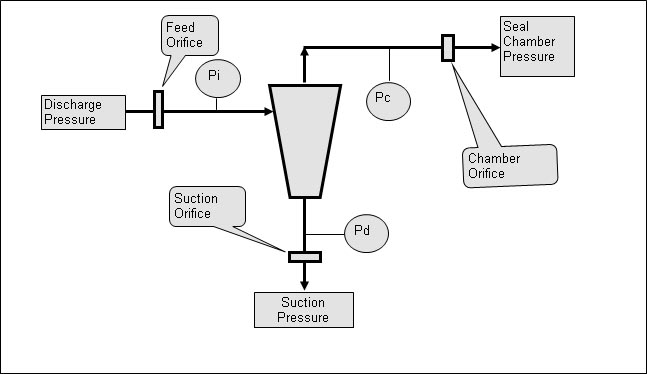
Most people do not realize that the cyclone separator in Plan 31 works best when the clean and dirty outlets – meaning the outlets at the separator itself — are at about the same pressure.  For this reason, Plan 31 really needs pressure gauges, orifices and/or control valves.  However, neither the API schematics nor my own illustrations show these gauges, orifice and valves.   Here’s a new illustration that I’ll be using.

Plan 31 with Orifices

A cyclone separator needs at least a 15 psi differential to work well.  However, if there is too much total differential pressure across the separator, then the centrifugal “streamlines” inside the separator become confused/turbulent and the separator does not work well.  Typically, a maximum total differential pressure of around 200 psi across the separator is recommended.  The orifices are used to set and control the differential pressure across the separator.

Long ago, I was called on to troubleshoot a pump/seal having a Plan 41 (Plan 31 with a heat exchanger).  To my surprise, I discovered that there was no flow to the seal.  Instead, flow was from the seal chamber to the cyclone and then to pump suction.  (I found this by feeling around the heat exchanger for differential temperatures.)

Even when designed and installed properly, Plan 31 does not remove all the solids from the pumpage (dirty) stream.  For example, the performance might be stated as something like “cyclone separator will remove 90% of all heavy solids having a diameter of 10 microns or larger.”  By “heavy” is meant that the solids should have a density more than twice that of the liquid.  Also, the concentration of solids should be less than 10%.  In addition, the cyclone separator does not do well in viscous fluids. 

So I don’t particularly like or recommend Plan 31.

TRL, API RP-691 and API 682

“TRL” is an acronym for Technology Readiness Level.  This is a new acronym for me.  I’m trying to learn more about it and its implications for mechanical seals — especially for API 682 5th Edition because the API lawyers are insisting that the TRL method and reference to RP-691 be added to API 682 5th Edition.

API RP-691 is a Recommended Practice from the American Petroleum Institute (API).  An API Recommended Practice is a document that communicates recognized industry practices.  In contrast to a Recommended Practice, an API standard appears to be much more binding and rigid.  API standards typically include references to Recommended Practices.

API RP-691 is titled “Risk-based Machinery Management”.  This 198 page document was published in June 2017 and is in its first edition.  It is available through API; costs $163 and can be purchased here.  Although I do not have a copy (and, apparently, API will not give a complimentary copy to the API 682 Task Force), RP-691 does not appear to have specific recommendations for mechanical seals.  It does, however, include pumps.  A preview of RP-691 is available here.  Be sure to click on the “Look Inside” icon to get a preview of RP-691.

In its description, RP-691 is said to define “the minimum requirements for the management of health, safety, and environmental (HSE) risks across the machinery life cycle. It shall be applied to the subset of operating company and/or vendor defined high-risk machinery.”  The proposed seal standard, API 682 5th Edition, certainly includes high risk machinery as defined in RP-691:  high temperatures, pressures exceeding 600 psig and specific gravities less than 0.5 even though all services may not be high risk.

From other sources, I learned that Technology Readiness Levels range from TRL 0 to TRL 9 with TRL 0 marking the beginning of research and TRL 9 being proven technology.  API appears to be assigning TRL 7 to machinery that has been used successfully in the field for three years.  That being the case, seals having been successfully Qualification Tested per API 682 would probably be assigned TRL 5 or TLR 6 but I’m just guessing at this point.

I have no objection to API inserting the reference to RP-691 into API 682 and it wouldn’t matter if I did.  I understand that the new TRL clauses are written somewhat generically in order to be inserted into other API standards as well.  I was told that the same clauses would be inserted into the next edition of the pump standard, API 610.  The API 682 Task Force was told that the paragraphs referencing RP-691 were mandatory and could not be edited or revised.  My concern is that, as written, the new clauses appear to completely overlook the Qualification Tests of API 682 and leave evaluation up to the judgement of the purchaser.  

Technology Readiness Level especially irritates me because, during the development of API 682 1st Edition, we were specifically told that field experience did not count.  As a result, the seal OEMs were forced into conducting expensive Qualification Tests by the API some 25 years ago and have spent many man-hours and millions of dollars on those tests.  If the TRL requirements had been available/required at the time of developing  API 682 1st Edition, not only would those requirements have been incorporated into the 1st Edition but there would have been no reason for developing, much less conducting, the Qualification Tests.  

Mechanical seals are a mature and proven technology.  Every seal OEM almost certainly has products that have been around for 30 – even 60 years – and also has many end users that have achieved 6 to 8 year MTBR with their products.  Therefore, a TRL rating of 7 for mechanical seals will quickly become the norm.  The TRL requirements will soon be taken for granted and become meaningless and ignored except that the TRL will take precedence over the Qualification Tests.

Obviously, passing a Qualification Test will not and should not result in a TRL higher than the rating of 7 granted for 3 years of actual service.  That being the case, why should a seal OEM bother with the Qualification Tests at all? I predict the demise of the API 682 Qualification Tests.

Here are some links for information about Technology Readiness Levels (TRL):

https://www.nasa.gov/directorates/heo/scan/engineering/technology/txt_accordion1.html

https://en.wikipedia.org/wiki/Technology_readiness_level

https://www.ncbi.nlm.nih.gov/books/NBK201356/

http://www.airforcemag.com/MagazineArchive/Magazine%20Documents/2016/August%202016/0816infographic.pdf

Thrust Load from Seals

The pressure surrounding the mechanical seal and its shaft sleeve imposes an axial force – a thrust – on the shaft.  This thrust load and direction can be determined by summing the products of the various pressures and areas of the seal and sleeve.  Fortunately, many of these products cancel each other out and the thrust load can be computed in a simple manner. 

The method shown below for calculating thrust load is taken from Chapter 17, “Seal Thrust Loads on Pump Shafts”, of Mechanical Seals for Pumps:  Application Guidelines from the Hydraulic Institute and Fluid Sealing Association.   Only the thrust load for single pusher seals is shown in this post but the book includes dual seals and bellows seals.

The general idea is that there is a hydraulic area between the balance diameter of the seal and the shaft upon which the seal chamber pressure acts to produce an axial thrust.  This hydraulic area is given by

where

    • A is the hydraulic “thrust” area, inch2
    • Db is the balance diameter of the seal, inch
    • Ds is the OD of the shaft, inch.

The thrust force is the product of the seal chamber pressure and thrust area.

The location of the balance diameter is illustrated below.

For many seals, the balance diameter can be estimated from the shaft size as follows:

  • Classic rotating seal:  shaft diameter plus 1/2” to 5/8”
  • Inverted rotating seal (made into stationary seal):  shaft diameter plus 5/8” to 1”
  • Stationary seal:  shaft diameter plus 5/8” to 1”.

These approximations to the balance diameter can be made because, typically, radial thicknesses, radial steps and even O-ring cross sections are based on 1/8” increments.  Radial clearances are often based on 1/16”; seals with large radial clearances may also have larger balance diameters.  Another variation comes from the shaft diameter not being an exact 1/8” increment and the sleeve may be used as an “adapter”.  Of course, the exact balance diameter depends on the seal design, thicknesses, clearances, etc. and the seal manufacturer should be consulted.

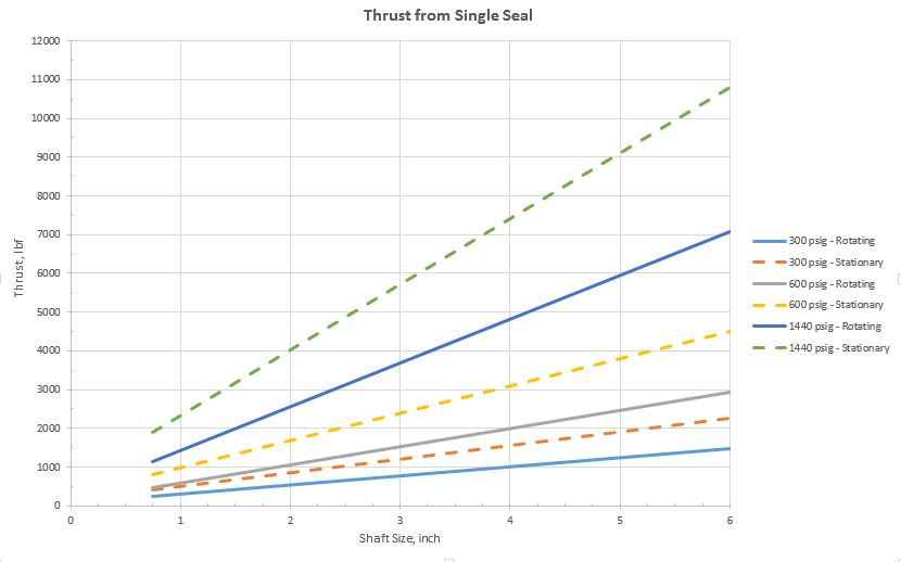
So, how much thrust is produced by the seal?  Sometimes, quite a lot – especially for large seals at high pressures.  The graph below is based on a classic rotating seal with balance diameter 1/2” larger than the shaft and a stationary seal with balance diameter 3/4” larger than the shaft.

Obviously, the thrust load estimated here for a stationary seal exceeds that of a rotating seal but this may not always be the case.  Again, the details of the seal design must be checked.  However, it is often the case that the thrust load from a stationary seal is larger than that from a rotating seal; therefore, it is best to consider a stationary seal configuration when making general assumptions about thrust loads.

This thrust load is transmitted to the shaft – typically by set screws – but devices such as pins, slots, grooves, split rings, etc. are sometimes used.  Therefore this thrust load is added to the thrust load imposed on the pump bearings.  Note that if the pump uses two seals (one on the driven end and one on the non-driven end) then the net thrust load from the seals that is imposed on the bearings may be zero.

Eventually, this blog post will make its way into the design pages of SealFAQs.  In a later post, we’ll take a look at the thrust capacity of set screws.

Just What is “The Seal” Anyway?

“Pump 101 is down and going to the shop.”

“What’s the problem?  The seal?”

We use the word “seal” to mean many things.  I’m just as guilty as anyone.  Usually, when I say “seal”, I mean the seal ring assembly. But sometimes I mean the combination of the seal ring and mating ring components.  Other times, I mean the assembled seal cartridge.  Especially when with others, I’ll go along with the conversation and say “seal” instead of “sealing system”.  I should know better and do try to be more specific but old habits are difficult to break.

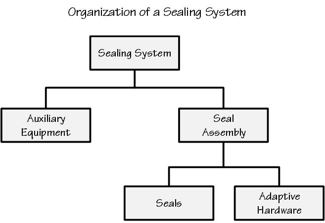
Below is an illustration of the way I try to think of a sealing system.

Auxiliary equipment includes coolers, reservoirs and even external circulating systems.

These days, the seal assembly usually means a cartridge assembly but it might mean the seal ring assembly.

Adaptive hardware consists of the sleeve, gland plate and various “adapters” that are necessary to fit a more or less standard seal ring and mating ring into the seal assembly and then into the pump.

And, no, that was not a lucky guess in the opening scenario.  Probably 60 to 80% of pump repairs are somehow related to the sealing system.

API 682 is Not a General Purpose Standard

In spite of all its excellent specifications, recommendations, tutorials, etc., etc., API 682 is not a general purpose standard for mechanical seals.  Here is a partial list of seals that API 682 does not address:

  • large seals
  • high pressures
  • mixer seals
  • rotary pump seals
  • wedge/chevron/ucup
  • outside mounted
  • common mating ring
  • shaft mounted
  • hook sleeve mounted
  • automotive water pump seals
  • stern tube seals
  • split seals
  • elastomeric bellows seals.

It appears that the 5th Edition of API 682 will include somewhat larger seals and higher pressures.  Mixers and rotary pumps could, of course, use API 682 seals provided those seals would fit into the seal chamber.  Wedges, chevrons or U-cups for dynamic secondary sealing elements were intentionally omitted in favor of O-rings.  Outside mounted seals were intentionally omitted in favor of inside mounted seals.  Shaft mounted seals and hook sleeve mounted seals were omitted in favor of cartridge mounted seals.  Dual seals using a common mating ring were omitted in favor of requiring a mating ring for each seal ring.  Automotive water pump seals as well as similar small utility seals and stern tube seals are far outside the scope of API 682.  Split seals have very different design for special applications and were never considered for inclusion in API 682.

Interestingly, API 682 does not address one of the earliest, most popular and proven mechanical seals:  the elastomeric bellows seal.  The omission of elastomeric bellows seals was intentional because some members of the 1st Edition Taskforce felt that elastomeric bellows seals were difficult to install.  This can be true; however, since API 682 considers only cartridge seals, installation of elastomeric bellows seals is simplified and furthermore would be done by the seal OEM.

Elastomeric Bellows Seal

In the mid 1930’s Crane Packing Company licensed a mechanical seal design from Chicago Rotary Seal. By the late 1930s, mechanical seals began to replace packing on automobile water pumps.  At first only the more expensive automobiles used mechanical seals in the water pump. The famous Jeep of WWII used a Crane elastomeric bellows seal in the water pump.  After WWII, all automobile water pumps used mechanical seals. Through several Crane patents, their design evolved into the full convolution elastomeric bellows seal of today.            

In 1943, under the direction of Carl E. Schmitz and designed by Russ Snyder, Crane Packing Company began work on what became its Type 1 and Type 2 rubber bellows mechanical seals.  Don Piehn, a draftsman still in high school, did the detailed drawings.  The Type 1 and Type 2 seal names were adopted about 1946.  Prior to 1946, Crane seals did not have number/type names.  The Crane seals that had been used in WWII jeeps and later other automobile water pumps came to be called the Type 3 and Type 4 but actually preceded the Type 1 and Type 2. 

Today, there are many manufacturers of elastomeric bellows seals.  Elastomeric bellows are very popular and also very reliable but they are not considered by API 682.

What Do You Want from Your Seal Supplier?

In the early 1970s, I was part of a centrifugal pump inspection team whose goal was to increase pump reliability.  At the same time, we were converting many pumps from packing to mechanical seals.  We were also converting some pumps with single seals to tandem seals.  We were a busy group and I was on a very steep learning curve.

Even though I was new to pumps and seals (well, bearings, lubrication, — ok, everything!) our group leader made no bones about what he wanted and expected from our seal suppliers:  SEALS.  That was just about it.  He expected our suppliers to have lots of spare parts on hand for essentially immediate delivery.

Of course, we also wanted to be kept informed of the latest developments in the world of seals.  We wanted to see lab tests, technical papers, advances in materials such as perfluoroelastomer and silicon carbide, etc.  Finite element analysis was beginning to be used to study seal design and performance.  This was an exciting time to be learning about mechanical seals.

In those days, we did our own failure analysis and we had plenty of failures to examine.  By our rules, Mean Time Between Repairs (MTBR) was only about a year (some would have called it 2 years or more).   Improvements in reliability through failure analysis was one of the main functions of the inspection group.  We used failure analysis to point towards specific and general methods of improving reliability.  We did not want to be simply “parts changers”. 

We also did our own seal repairs, including lapping, and rebuilt our own seals.  Training was done by our group leader.  I actually heard him say, somewhat arrogantly, to a seal salesman:  “What can you teach me about seals?”  But then, he enjoyed challenging people – including our own group members.  We actually did go to a few outside, independent seals training courses and sometimes even asked a seal OEM for a detailed failure analysis report.  But, for the most part, we did not rely on the seal OEMs.

Of course, we had our own inventory of critical pump and seal parts in addition to the seal supplier’s inventory.  The relative proportions of these inventories were always a bone of contention.  I have to laugh when someone says that, long ago, inventory did not matter.  Of course inventory mattered – the “optimum” was simply a different amount than it is today.

We even had an equipment records system that used a computerized database (yes, even in the ‘70s!) of equipment, services and repairs.  Querying this database provided statistical evidence of problem pumps and problem components.  Yes, mechanical seals were the main component causing pump repairs.  In addition to the computer databases, we also had good old paper files for each pump which included the original specifications and datasheets, notes on repairs and, occasionally, a photograph but more often a sketch.

I realize that every process plant was not so well staffed, directed and equipped but mine was and I have greatly benefitted from that experience.

Fast forward some five decades and the relationship between seal supplier and end user is vastly different.  Most end users do not do failure analysis and do not rebuild their own seals.  They may not have their own equipment databases and failure records.  They even may not have an inventory of seal parts.  Instead, most end users seem to rely on their seal suppliers to provide not only goods but also services.

As a result of the changes in this relationship, it is the seal supplier who gains the experience and the knowledge that I received as an end user.  The seal supplier typically provides a technician or engineer, very nearly a contract employee, to his customer, the end user.  This person collects data, examines seal failures, makes recommendations (and gets to see the effect of those recommendations!) and builds up an equipment and failure database.  The loss of experience for the end user is definitely a gain in experience for the seal supplier.

So, what do you want from your seal supplier?
Inside–Mounted vs Outside–Mounted Seals

Inside-mounted and outside-mounted seals are described as part of SealFAQs “Basics” pages under Classification by Configuration.

The vast majority of all seals fall into the single seal category. Single seals can be mounted inside the process liquid or outside the process liquid. 

Inside-mounted seals are sometimes described or even defined as being mounted within the boundaries of the seal chamber.  This means that the process fluid is present on the outside diameter of the seal.    Inside-mounted seals are easy to cool and are capable of sealing high pressures.  The direction of leakage is from the OD to the ID of the seal face; centrifugal force opposes leakage.  Inside-mounted seals are by far the most popular.

Outside-mounted seals are sometimes described or defined as being outside the boundaries of the seal chamber. Process fluid is therefore present on the inside diameter of the seal and outside-mounted seals can have minimal contact with the process liquid.  The direction of leakage is from the ID to the OD of the seal face; this is the same direction as centrifugal force and outside-mounted seals often leak more than inside-mounted seals.

The concepts of inside-mounted and outside-mounted positions can be and are extended to the outer seal of a dual seal arrangement.  That is, the outer seal is either inside-mounted with respect to the containment chamber and buffer/barrier fluid or outside-mounted with respect to the containment chamber and buffer/barrier fluid.

The effects of centrifugal force on leakage are very real but usually small in magnitude and are typically neglected in calculations.

Both inside and outside-mounted can be designed with a balance ratio to keep the faces closed; however, sometimes seals that were really designed to be inside-mounted are simply applied as outside-mounted seals and the balance ratio may not be appropriate.  Such applications should be used only at very low pressures.

API 682 is about inside-mounted seals but the terminology has been changed to “internally-mounted”. 

  • In 1st Edition, the standard seals are described as “inside-mounted” for Arrangements 1, 2 and 3 in Paragraphs 2.1.4, 2.1.5, 2.1.6.  This was done intentionally and very little discussion was needed.  No one wanted “outside-mounted” seals.
  • In 2nd and 3rd Edition, the definitions of Type A, B and C seals described them as “inside-mounted”.
  • In 4th Edition, Types A, B and C are specified to be “internally-mounted” in clause 4.1.3.

The advantages of an inside-mounted seal include:

  • Faces effectively cooled by a flush directed at the OD
  • Seal chamber environmental controls act on the seal
  • Leakage is opposed by centrifugal force
  • Leakage management can be incorporated into the gland plate
  • Rotation tends to keep heavy debris away from the faces.

The disadvantages of an inside-mounted seal include:

  • Equipment must be disassembled in order to install the seal
  • Can be difficult to install, especially if non-cartridge design
  • All/most materials used must be corrosion resistant to the process fluid
  • Seal chamber must have adequate room for seal.

The advantages of an outside-mounted seal include:

  • Easy installation, especially for non-cartridge designs
  • Seal can be observed directly while in operation (careful!)
  • Seal can be adjusted without disassembling equipment (careful!)
  • Less contact with corrosive process fluid
  • Often used for split mechanical seals.

The disadvantages of an outside-mounted seal include:

  • Poor heat transfer limits seal to low speeds and pressures
  • Leakage management can be difficult.

I have disliked outside-mounted seals for many years because of an early bad experience.  I barely knew what a pump was – much less a mechanical seal – and was starting my machinery education with a plant tour.  Usually an office engineer, I was wearing the required safety equipment of those years:  safety glasses, a hard hat and a long sleeve shirt.  My shirt was a nice new one.  The technician escorting me excitedly waved me over to a pump.  “You wanted to see a seal in action, well here is one.” He pointed to outside-mounted seals on both the main and spare pump.  I could see the details of the seal on the idle spare pump and also watch the main pump seal in operation.  He explained that, in addition to observing the seal in action, it was also easy to install.  I was impressed and wondered why more seals were not mounted outside the seal chamber.   A few days later, my wife held up my new shirt, now full of holes, and asked what I did to it.  The pump and outside-mounted seal I had been examining were handling caustic and the seal had a slight leak which, because of shaft rotation, had been spun onto my shirt.  My wife then explained to me why outside-mounted seals should be avoided.  Of course, some sort of shield or deflector could have been placed around that outside-mounted seal but I’ve simply not used outside-mounted seals ever since that bad introduction to them.