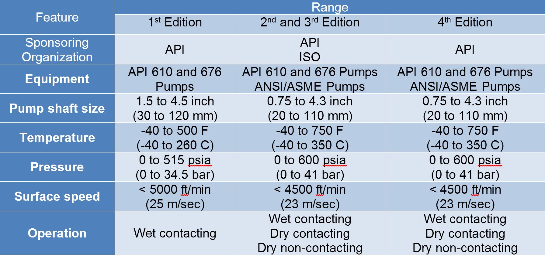
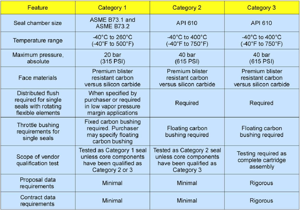
After many years of planning, the American Petroleum Institute (API) released the Fourth Edition of API 682 in May 2014. The API 682 standard, which dates back to 1994 and is formally known as Shaft Sealing Systems for Centrifugal and Rotary Pumps, offers specifications and best practices for mechanical seals and systems to operators of pumps. The 4th edition began to take shape in 2006, when API formed a 4th edition task force to respond to end users’ questions and comments about previous editions. The task force soon realized that major changes, including reorganization and editing, would be necessary.
Those who use API 682 should understand the standard’s scope and remember that the standard doesn’t include specifications for equipment outside that scope, such as engineered seals or mixers. Another important but often misunderstood point is that API 682’s figures are illustrative and not normative in their entirety.
The scope of 4th edition is identical to 2nd and 3 edition except that the ISO Organization is not involved.
Although there was pressure from the API 610 Committee to include larger pump shaft sizes, the size range remained the same as 2nd and 3rd edition. Maintaining the original shaft sizes was considered important because of the detailed nature of the API 682 specifications.
Any seal which is outside of the scope of the standard (by design or operating window) is defined as Engineered Seal. An Engineered Seal is not a seal Type but rather identification that special design features may be required to meet the application conditions. The seal OEM is free to deviate from any or all of the requirements of the standard in order to design an appropriate seal. There are no special qualification testing requirements for an Engineered Seal.
Configurations
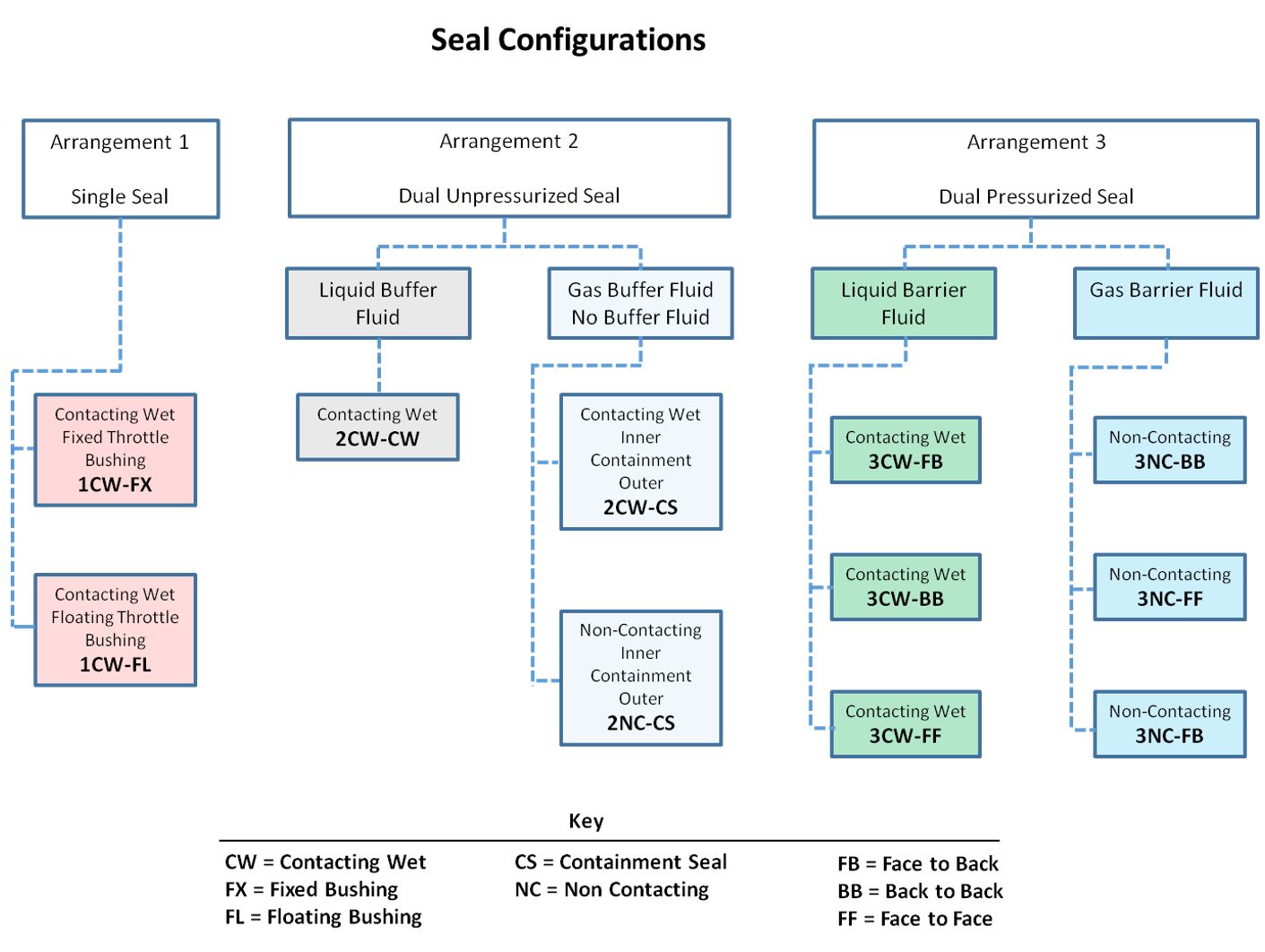
Seal Configuration refers to the orientation of the seal components in an assembly. In previous editions, these were defined as face-to-back, back-to-back, and face-to-face and these terms are carried over into the Fourth Edition. In theory, any orientation (face to back, back to back, face to face) can be used in a dual seal. However, note that acceptance of any orientation is not necessarily the same as endorsement because each orientation has advantages and disadvantages with respect to certain applications, performance and survival of upsets.
Clearances
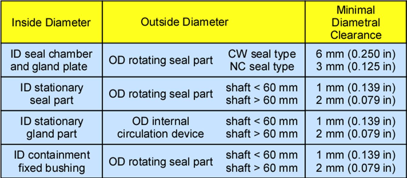
Before the 4th edition, API 682 did not specify a minimum clearance between the inside diameter of a stationary seal part and the outside diameter of a rotating seal part. The 4th edition specifies this minimum clearance – typically the clearance between the sleeve and the mating ring. Clearances specified are representative of standard clearances that have been used for decades. Seal components are not to be considered as “shaft catchers” to restrict shaft movement. The minimum clearance specified in API 682 applies only to equipment within the standard’s scope. Equipment outside that scope, such as non-cartridge seals, older pumps, non-API 610 pumps and certain severe services, might benefit from larger clearances.
Codes
Once again, seal codes have changed. The new code, described in Annex D, is probably the best to date and includes some concepts and codes from the historical API 610 seal code. The new code uses eight fields:
- Seal category
- Seal arrangement
- Seal type
- Containment device
- Gasket material
- Face material
- Approximate shaft size (in millimeters)
- Piping plan
Piping Plans
Annex G of the 4th edition is generally reorganized and includes six new piping plans:
- Plan 03 gives purchasers the option of using the seal chamber’s special features to enhance circulation or venting in the machinery.
- Plan 55 is an externally circulated buffer (unpressurized) fluid for Arrangement 2 seals.
- Plan 65 is now subdivided into 65A and 65B. Plan 65A is used to detect an excessive leakage flow rate and Plan 65B to detect a certain amount of cumulative leakage.
- Plans 66A and 66B are new to the standard, although end users have used them previously in pipeline applications. These plans detect and restrict excessive leakage rates in case of an Arrangement 1 seal failure.


