Tag Archives: API 682

Hydrostatic Pressure Test

Apparently, the rules and guidelines for conducting a hydrostatic test on pressure vessels – including pumps – are about to be changed.  Perhaps those rules have already been changed and I’ve simply missed hearing about them.  I blame that on retirement.

The hydrostatic test is the way in which pressure vessels are tested for leaks.  The test involves filling the vessel with a liquid, usually water, and pressurizing it to the specified test pressure.  In my career, the rule for determining the hydrostatic test pressure has been to simply multiply the Maximum Allowable Working Pressure (MAWP) by 1.5.  That is, suppose a certain vessel has an MAWP of 600 psig; it would be hydrostatically tested at 900 psig.  Of course, there are other details such as the duration of the test, variations based on operating temperature, etc.  But basically, the hydrostatic test pressure has been 1.5 x MAWP for many years – certainly since the 1950s.  However, it has not always been that way.

Here’s an interesting little anecdote that I was told many years ago.  I may not have it quite right and, for all I know, it may not even be true, but here goes.  In the 1970s, I was told that very long ago, the practice was to test pumps at 2 x MAWP.  Perhaps this was because pumps are manufactured from castings.  Anyway, there was a pump standards meeting (perhaps this was even an early form of an API standards meeting) and a requirement was written to hydrostatically test pumps at 1.5 x MAWP.  After the meeting, the chief engineer for a major pump manufacturer was buying drinks for everyone at the bar.  Surprised by his generosity, a fellow committee member remarked that the 2x hydrostatic test must have been difficult.  “Not at all”, said the chief engineer, “In fact, I just increased all my pressure ratings by 33%!”  That is, pumps previously rated for 600 psig MAWP but hydrostatically tested at 1200 psig could still be hydrostatically tested at 1200 psig but then rated for 800 psig MAWP!

I’ve been told that the multiplication factor for determining the hydrostatic test pressure will be changed from 1.5 to 1.3 according to the ASME Pressure Vessel Code Section VIII.  Apparently this will be applied to both pumps and piping.  The same multiplier will probably be used for API 682 reservoirs such as are used with Piping Plan 52 and 53.  The pertinent 4th Edition clauses for reservoirs now read:

8.3.6.2.8 The reservoir is part of the pump piping system. Unless otherwise specified or required by local code, the reservoir shall be designed, fabricated, and inspected in accordance with ISO 15649 or ASME B31.3 using piping components.

8.3.6.2.9 If the reservoir is built entirely of piping components, ISO 15649 or ASME B31.3 can be applied and provides adequate design for the reservoir just as it does for the pump suction and discharge piping. It is the user’s responsibility to ensure that local codes do not require that reservoirs be built in accordance with a pressure vessel code such as EN 13445 or ASME VIII, Division 1.

With this wording, the default is a pipe based reservoir but an ASME certified reservoir is an option.  I hope we will be able to continue this approach in 5th Edition but I’m uncertain about higher pressure reservoirs.  From my past experience, old notes and browsing, here’s what I’ve learned.

ASME Certified Pressure Vessels

ASME certified pressure vessel fabricators undergo a rigorous program to ensure compliance with the rules and regulations of the ASME Boiler and Pressure Vessel code.  For unfired pressure vessels, these requirements are given in ASME VIII, Division 1 (EN 13445).  There are two variations of certification:  “U” stamp and “UM” stamp.

“U”stamped pressure vessels are required to have a 3rd party ASME inspector review and approve the calculations as well as inspect certain stages during manufacture of the reservoir.  This inspector also witnesses the ASME hydrostatic test which, apparently, is now 1.3 x MAWP.  This means that U stamped vessels cannot be manufactured in advance; that is, the U stamped vessel is customized for a particular service, has a serial number and therefore cannot be a stocked item. The fabricator undergoes an ASME inspection every three years.

In contrast to the U stamped vessels, there is a “UM” stamped vessel which is also subject to the same ASME specifications.  However, the “UM” stamped vessel is limited to a maximum of 1.5 cubic feet for a 600 psig rating and 600 psig is the maximum permitted pressure for the UM stamp.  ASME 3rd party inspection is not required; therefore “UM” vessels can be manufactured in advance, they do not have a serial number and they can be stocked as an inventory item.  The UM fabricator is inspected annually by ASME.

Pipe Based Reservoirs

Pipe based reservoirs for API 682 sealing systems must be built entirely of piping components and ASME B31.3, “Process Piping”, (ISO 15649) is the governing standard.  As far as I can tell, ASME B31.3 now requires hydrostatic testing at 1.3 x MAWP.

Mechanical Seals

It should be noted that the mechanical seal is not considered to be part of the pump pressure vessel and therefore does not fall under the pressure vessel rules.  Seal manufacturers have several pressure ratings for their products.  API 682 recognizes a static pressure rating, a dynamic pressure rating and a hydrostatic pressure test rating (see the SealFAQs version of these definitions).  Each seal OEM seems to use a different and proprietary method for determining these pressure limits.

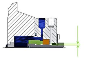
 

API 682 Mating Ring Clearances

Mating Ring Clearance Illustration

Before the 4th Edition, API 682 did not specify a minimum clearance between the inside diameter of a stationary seal part and the outside diameter of a rotating seal part. The 4th Edition specifies this minimum clearance – typically the clearance between the sleeve OD and the mating ring ID. The clearances specified in 4th Edition are representative of standard clearances that have been used for decades.  I’ve written a historical perspective on how those sleeve to mating ring clearances came to be.

It should be emphasized that the minimum clearance specified in API 682 4th Edition applies only to equipment within the scope of the standard. Equipment outside that scope, such as non-cartridge seals, older pumps, non-API 610 pumps and certain severe services, might benefit from larger clearances.

API 682 “Engineered Seals”

The term “Engineered Seal” is widely misused and misunderstood with respect to API 682.  Let’s see how this came about.

API 682 imposes a wide range of design details for mechanical seals including materials, clearances, and design elements; however, it is not all inclusive of all seals and services. The 4th Edition Taskforce believed that this subset of details was prudent for seals which would be applied within the scope of the standard.   At the same time, the Taskforce recognized that at higher pressures, temperatures, speeds, or sizes the design details of the standard might be inappropriate for the intended application.   Outside of this scope, the seal OEM is permitted, even encouraged, to deviate from the prescribed requirements and to “engineer” a seal with specific characteristics that are appropriate for the specific out-of-scope application. By definition, this special seal will then not fall into the strict definition of a Type A, B or C seal – it is an Engineered Seal.

So, what is the scope of API 682 4th Edition and what is the official definition and description of an “Engineered Seal”?

The Scope of API 682 4th Edition is, or should be, given in Section 1, “Scope”, of the standard.  As written in Section 1, the scope includes pump shaft diameters between 0.75 and 4.3 inches; unfortunately, Section 1 does not address pressure, temperature or speed.

The official definition of an “Engineered Seal” per API 682 4th Edition, Clause 3.1.29 is:

Mechanical seal for applications with service conditions outside the scope of this standard.

NOTE Engineered seals are not required to meet any of the design or testing requirements of this standard. See 4.1.3 and A.1.2.

Why are Engineered Seals not required to meet any of the design or testing requirements of API 682?  Simple: standards cannot impose requirements on things that are outside the scope of the standard.  For example, a standard limited to a scope of, say, 600 psig would not state “for higher pressures, double the thickness of everything”.   Similarly, API 682 cannot state “Even though a seal may not be intended to be in accordance with this standard, it still shall meet the design and testing requirements of this standard”.

Section 4 is about sealing systems.  Clause 4.1.3 defines seal types — A, B and C — and notes that Type A and B are suitable for temperatures up to 350 °F whereas Type C is for temperatures up to 750 °F.  Clause 4.1.3 then states that seals outside the scope of Type A, B and C are termed engineered seals.  Although “Engineered Seal” is sometimes written as “ES”, there actually is no “Type ES” seal.  Seal type is either Type A, Type B or Type C.

It is worthwhile to note that pressure limits are included in the definition of seal category which is given in Clause 4.1.2.  Category 1 is limited to 500 °F and 300 psig whereas Category 2 and 3 are limited to 750 °F and 600 psig.  These limits are usually taken as part of the scope of API 682 but were not included in Section 1.

Annex A is an informative annex entitled “Recommended Seal Selection Procedure”.  However, since Annex A is informative, it cannot not impose any requirements.  Clause A.1.2 is entitled “Additional Engineering Required” and is a list of eleven concerns which might provide reason for a more detailed engineering review of the seal.  The list includes size, speed, temperature, pressures and seal chambers that are outside the scope of API 682 4th Edition.  Again, this list is informative, not normative.

To my way of thinking, an Engineered Seal is simply an “other” with respect to API 682 and shows attention to detail for a particular service that is not otherwise included in the scope of API 682. As a practical matter, API 682 Engineered Seals typically have some basis in API 682 — certainly that is the expectation of the Purchaser.  But again, as noted previously, API 682 cannot impose requirements on these out-of-scope designs.

An otherwise true API 682 seal is still an API 682 seal even if the seal chamber does not precisely conform to the API 682/610 dimensions.  Here is an example:  Suppose a seal OEM has designed a product that (somehow!) fulfills every requirement of API 682 when fitted into the proper seal chamber.  However, someone wishes to use this API 682 seal in a pump having a smaller seal chamber.  The API 682 seal fits into the chamber but its clearances no longer meet API 682 requirements.  The seal OEM could

  • Offer its standard API 682 design but take exception to API clearances
  • Offer a custom version of its standard API 682 design that meets API clearances in this particular pump but
    • Has a reduced pressure rating
    • Does not have multi-point injection
    • , etc.

The “custom” seal would be an API 682 “Engineered Seal”.  It is (most likely) a one-off design that has never been tested.  In a similar manner, an existing API 682 seal might be tweaked (materials, balance ratio, flush design, etc.) for somewhat higher pressures or temperatures as a one off “Engineered Seal” but never tested – it would be an Engineered Seal.

I hope that the 5th Edition of API 682 does a better and more concise job of defining the scope of API 682 as well as an “Engineered Seal”.  I believe that the “scope” of 5th Edition is likely to be clarified as well as expanded and therefore the need for “Engineered” seals will be reduced.  I’m on the taskforce and will be trying to do my part to make this happen.

SealFAQs statistics for June 2018

SealFAQs has now been officially launched for six months.  In June, unique visitors decreased slightly from May by about the difference in the length of the month and the fact that June had five weekends whereas May had only four.   Here are the statistics according to Awstats (Advanced Web Statistics).

SealFAQs had 1149 unique visitors during June and a total of 1847 visits (1.61 visits/visitor).  Visitors averaged looking at 4.7 pages per visit – a significant increase.  Bandwidth was up to 1.1GB.

Visits per day during June increased from the May average of 60 to 61 with the most visits in a day being 87 – twice!  As usual, most people visit during the week and the middle part of the day.

By far, the most visitors are from the United States and distantly followed by India, Russia, South Korea, Poland, China, Canada and others.

The average time of a visit has increased to 442 seconds in duration but 77% of all visits are still for less than 30 seconds.  It appears that some people are logging in and staying on the site an hour or more.

Access to SealFAQs via search keyphrases was down a little with 5 different keyphrases including “api 682”.  The most common keyword is “seal” of course.

June was a decent month for SealFAQs with some gains in viewing.

Wikipedia: API Standard 682

Although Wikipedia, the online encyclopedia, has a page for the American Petroleum Institute (API), it does not have a page for the seal standard API 682.  I’ve created a new page “API Standard 682” and written an encyclopedic type description.  Because this is a new page, it must be approved and I was told that approval might take several months because of the large backlog of new pages (2415 pending submissions!) waiting for approval.  In the meantime, the draft page can be accessed by searching for “Draft: API Standard 682” or by going directly to https://en.wikipedia.org/wiki/Draft:API_Standard_682.  The draft article can even be edited if you wish to revise or add to it.

The draft article on API 682 does not contain nearly enough detail to replace the complete standard and is not intended to do so. Instead, the draft article builds up to the content of 4th Edition by providing the background and development of previous editions.  The draft article includes the Table of Contents for 4th edition and a brief descriptions of piping plans.

Whereas the terms “tandem” and “double” were used in the more general “End Face Mechanical Seals” article, I used the terms “Arrangement 2” and “Arrangement 3” in the API 682 article.

At this point in time, the Wikipedia draft page on API Standard 682 is in sync with SealFAQs but you can be sure that will change in the future.

Wikipedia: End Face Mechanical Seals

Wikipedia, the free online encyclopedia, has a page about mechanical seals:  “End Face Mechanical Seals”.  The “End Face” term is to distinguish the “mechanical seals” that are featured in SealFAQs from the many other types of seals and mechanical seals that are also on Wikipedia.

The Wikipedia page on end face mechanical seals is a pretty good one – I know because I wrote much of it. In fact, some years ago, I edited the page and convinced other editors to use the term “end face mechanical seals”.  Of course, Wikipedia is a collaborative effort and anyone can edit Wikipedia articles so much of my previous revisions had disappeared – just as my current revisions will also disappear over time.

This time around, my edits were largely to make the Wikipedia article consistent with API 682. Therefore, I insisted that an end face mechanical seal is comprised of five components:

  • Seal ring
  • Mating ring
  • Secondary sealing elements
  • Springs
  • Hardware

whereas the previous article had listed only four components by virtue of grouping the seal ring and mating ring into “primary sealing surfaces”. This combining has happened in the past and will probably happen again.  Obviously someone believes strongly in grouping the seal ring and mating ring.

I also added a very brief overview of seal piping plans, expanded the section on origins and development of mechanical seals and provided a list of references – including a link to SealFAQs.

At this point in time, the Wikipedia page on End Face Mechanical Seals is in sync with SealFAQs but you can be sure that will change in the future.